


Tube-and-fin heat exchangers usually consisting of 4–12 rows of tubes…
Tube-and-fin heat exchangers consisting of 1–4 rows with typical entering water temperatures between 120˚-180˚. As cold air passes across the coil and contacts the hot fin surface, heat transfer occurs.
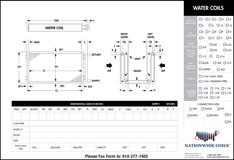
Yes, airflow matters. Water coils need to be piped for counter flow with the return being on the entering air side of the coil and the supply being on the leaving air side of the coil. This allows the return water to temper the warmest entering air getting it closer to its set point prior to leaving the last row where it will see the coldest supply water temperature. The reason for this is counter-flow which maintains the maximum temperature difference across the coil throughout the time the air is passing through the coil. Without proper counter-flow there will be capacity loss estimated at 1-2% per row.
You want to make sure you don’t go over 550 FPM on the face velocity. If your coil fin height is above 42”, an intermediate drain pan should be utilized. If 550 FPM of face velocity cannot be achieved, then moisture eliminators may need to be mounted on the leaving air side of the coil.
Rows are counted horizontally across the coil. Even though tubes are staggered horizontally they are not staggered vertically, each section of vertical tubes counts as a row.
Tube-and-fin heat exchangers usually consisting of 4–12 rows of tubes…
Built to rigorous specifications for efficient heat transfer that's ideal for outdoor use…
Designed to be used in air-side applications for cooling, heating and dehumidifying…